Raspberry Pi GPIO Pinout: What’s The Use Of Each Pin On Your Pi?
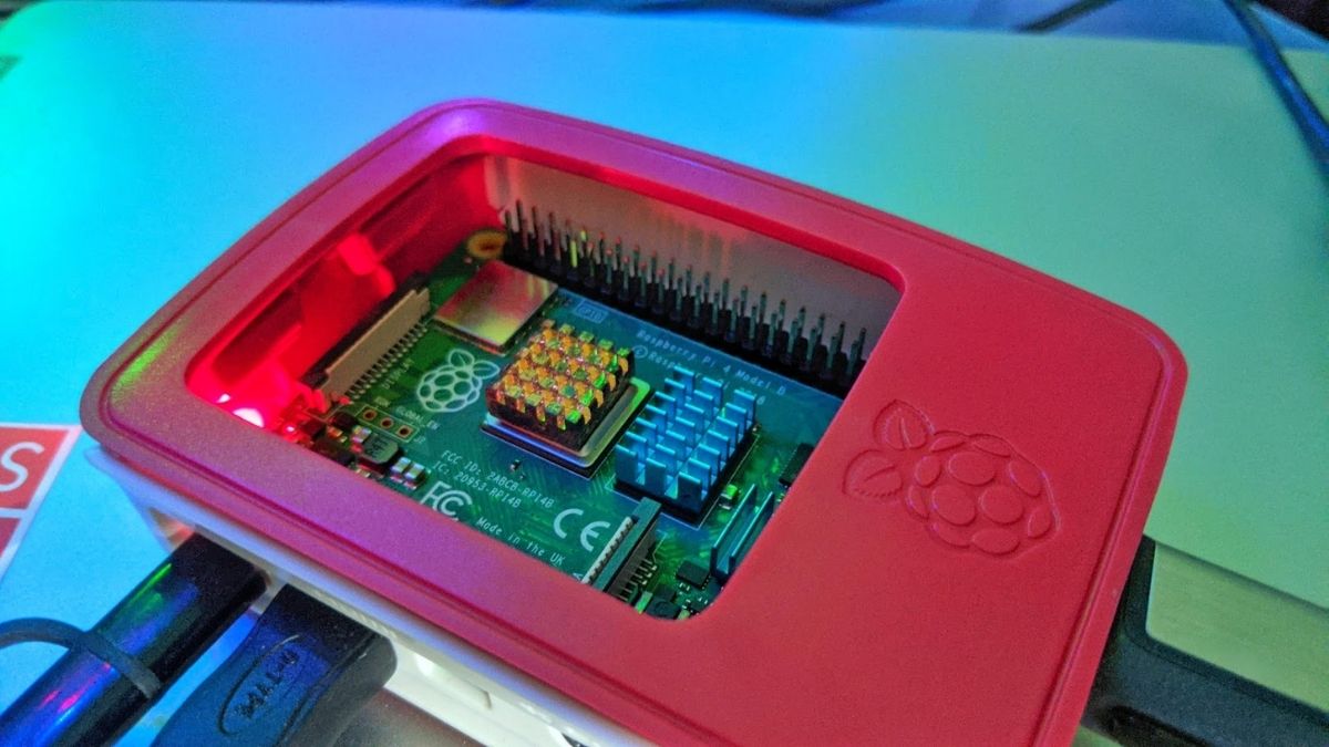
Raspberry Pi is one of the cheapest computers in the world today, with the latest version, the Raspberry Pi 4 B, starting at just $35. It’s not just the price but also the price-to-performance ratio, which is also quite impressive. One of the amazing features is the Raspberry Pi GPIO pinout, which makes the Raspberry Pi famous among DIY enthusiasts.
If you want to buy one, make sure to check out our Raspberry Pi 4 Model B review. This article will look at these GPIO pins’ functionalities and what you can do by using them. Now, each Raspberry Pi comes with a different number of GPIO pins, but we’ll be elaborating about the ones specifically on the latest Raspberry Pi 4 B. In case you own a different RPI, we’ll leave links to their descriptions in the article. Now, let’s get started.
Raspberry Pi GPIO Pinout: What Are GPIO Pins?
The term GPIO in Raspberry Pi stands for General Purpose Input Output which, as the name suggests, allows you to connect different electrical circuits and components, build amazing things, and learn along the way.
There are 40 GPIO pins on the Raspberry Pi 4 B, which have two states – On and Off. These states can be controlled by programming languages like Python. Here a list of the types of pins.
| Types and total pins | Use |
|---|---|
| Power 2 x 5V pins and 2 x 3.3V pins | As the name suggests, these pins are used to supply power to external components. |
| GPIO | General-purpose I/O pins are used to turn devices like cameras, LEDs on and off. |
| GND | GND stands for Ground and is used to provide grounding to the circuits |
| UART | Universal Asynchronous Receiver/Transmitter pins are used for serial communication to transmit and receive serial data. |
| I2C | I2C pins allow us to connect sensors. These pins also have a fixed 1.8 kΩ pull-up resistor to 3.3v. |
| SPI | Serial Peripheral Interface Bus pins are also used to connect external accessories but with a different protocol. |
Raspberry Pi pin layout (diagram)
Here’s what the Raspberry Pi pin layout looks like:
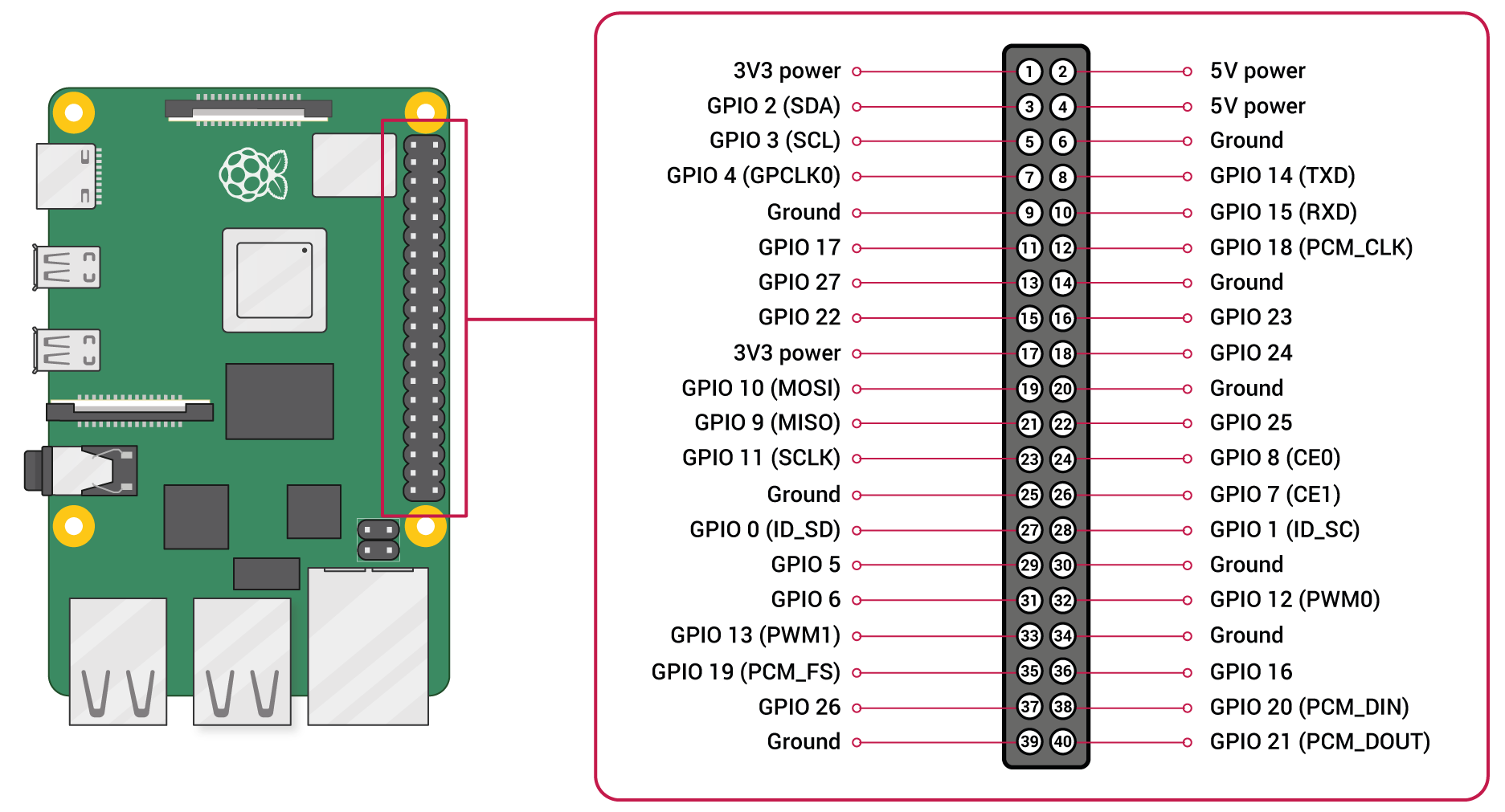
As you can see from the above diagram, the pin numbering starts from 1 and goes up to 40. Here’s an explanation of what each type of pin in the Raspberry Pi GPIO pinout does:
1. Power Output Pins (3.3V – 1,17) ( 5V – 2, 4)
Raspberry Pi 4 B comes with two kinds of power output pins – two lower voltage 3.3V pins and two 5V pins.
The 5V pins are directly connected to Raspberry Pi’s power input. Hence the 5V pins can supply the whole power adapter’s current minus the power used by the Raspberry Pi. You won’t be able to power the accessories that need more current. Instead, you’ll need to connect them to the outer power supply.
The 3.3V pins offer less power output. For example, let’s take the fan accessory, which plays an important role in keeping the Raspberry Pi 4 cooler and functional for a longer usage period.
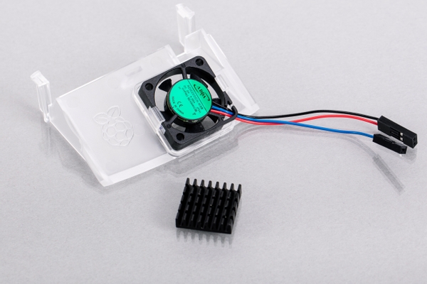
The fan accessory runs at two speeds, 3500 RPM and 5500 RPM, and comes with two connecting wires – red and black. If we connect the red wire to Pin 1 (3.3V) and the black wire to the GND pin ( Pin 9, 6), the fan will operate at 3500 RPM. Connecting the red wire to Pin 2, the fan will draw more power and operate at 5500 RPM for more effective cooling.
If you want to know how effective the fan accessory works, do make sure to check out our Raspberry Pi 4 Model B review (linked earlier in the article).
2. Ground Pins (6, 9, 14, 20, 25, 30, 34, 39)
There are a total of 8 ground pins in the Raspberry Pi GPIO. You generally find three-pin plugs on larger electronics like refrigerators and ovens. Have you ever wondered why?
The third and usually the top-most pin is called neutral and optional, but it is recommended to have it as it can probably save you thousands of bucks if there’s a surge in electricity. Without it, your electronic device would be toast in seconds. The same is the case with Raspberry Pi.
It is important to connect external circuits to the ground pins, or else you might end up burning the parts or, in the worst case, even your Raspberry Pi.
3. GPIO Pins
Everything else apart from power and grounding pins is GPIO pins. Raspberry Pi GPIO voltage is 3.3V when set to output mode.
These pins will allow you to connect external devices like sensors and cameras to send and receive data using the same. GPIO pins are quite similar to what we find in Arduino, i.e., digital pins.
There are two ways to configure a GPIO pin, i.e., to set them to either input mode or output mode. The input mode allows you to read a value from the external device.
Setting GPIO pins is done by importing the GPIO module in Python. Here’s the code to set the pins to input and output:
GPIO.setup(pin, GPIO.IN) #input
GPIO.setup(pin, GPIO.OUT) #output
You can also choose to either give out 3.3V or give no output power through specific pins using the code.
GPIO.output(pin, 1) #3.3V
GPIO.output(pin, 0) #0V
Now, not all the GPIO pins are made equal. There are specific protocols on some of the GPIO pins that could help transfer way more information.
I2C Protocol (3, 5)
This protocol’s main usage is to receive the information from an outer device and activate other devices or components. I2C is present in pins 3 and 5, i.e., SDA (Serial Data) and SCL (Serial Clock).
As you can guess, SDA is responsible for carrying the data, and SCL synchronizes the data transfer between the devices.
UART (8, 10)
Pins 8 and 10 are UART pins. For starters, UART stands for Universal Asynchronous Receiver/Transmitter, whose main purpose, as you might have guessed, is to transfer and receive serial data asynchronously
In simple terms, you’ll be able to connect other devices that also have Transmit and Receive pins. Say, another Raspberry Pi or Arduino where you can connect the Transmit pin to the receive pin on the other device and vice versa. Pretty cool, right?
SPI (19, 21, 23, 35, 24, 26, 36, 38, 40)
Like I2C, SPI is also a protocol used to send data. So, “How is it different from I2C,” you ask?
Well, you see, not every sensor communicated through the same protocol. Even if you have many sensors that use a particular protocol and in case you run out of space, you can use the SPI protocol to connect them.
SPI has four types of pins, namely:
- MOSI – Master In Slave Out (Send data to Slave from Master
- MISO – Master Out Slave In (Send data to Master from Slave)
- CS – Chip Select (Select the slave to send and receive the data)
- SCLK – Clock
Summing Everything Up
If you want to acquire more in-depth knowledge of these pins, visit pinout.xyz. So, These were some of the basic terminologies that you need to understand before jumping into doing projects with Raspberry Pi. Always make sure to be extra careful while connecting wires and pins. One bad pin connection and your Raspberry Pi could get damaged.