Routing: How Do Packets Travel And What Happens Inside a Router?
If we talk about the computer networks, then it is incomplete without Routing. It is often said that the Routing is the backbone of the computer networks.
Routing is the process of finding a path between two nodes in a network based on certain criteria such as the shortest path or the fastest path etc. Modern routing algorithms strive to find the best path between the source and destination.
Before we go into the details, it is necessary to understand the basics of the computer networks. Though we recommend you going through our OSI layer article first, however, we can go beyond it and dive really into fundamentals of routing.
Router Interfaces:
It is necessary to understand that each interface of a router connects to an IP network. But each interface would also have their own IP address for communication. Also, two interfaces connected together has to be there on the same subnetwork. Can you tell why?
Switch Interfaces:
Switches interfaces connect to different hosts on a local area network. It uses ARP for packet delivery which utilizes the MAC address of different hosts on a local area network for the data delivery. Before we proceed any further, here is a simple question that you might want to answer for yourself:
Do Switches need IP addresses for communication? If yes, then why and in what cases; if not, then why not and in what cases.
Well, it all depends. Here are the three scenarios which should give you some ideas about Switches.
Types of Switches:
Basic Switches:
Basic switches are those ones which are usually used for the domestic purposes. For example, a switch that you buy for a better connectivity inside your house might be a basic one. They are mostly kind of plug and play switches. Here, you can know more about the Layer 2 basic Switches.
Moderate Level Switches:
These switches are a bit more expensive switches than the ones we discussed in the previous paragraph. These Switches have the options to provide you with some web interfaces using which you can do things like adding names to ports, setting up VLAN numbers on different ports, defining trunk interfaces, applying speeds and duplex settings on various interfaces, etc.
Manageable Switches:
These switches are the expensive ones and advanced of all. They have multiple switch settings. At the advanced level, they can even support layer 3 activities such as routing, MPLS, advanced STP. These Switches are often called layer 3 Switches.
After the switches, we come down to individual hosts. An individual host on a network could be any networking device with its own unique IP address. For example, it could be your laptop, tablet, a router interface, a server, etc.
Now we are ready to move further on “How do packets travel in a network?”
Broadly, there are two ways in which the packets can be made to reach from the source to destination in the network. Those two methods are called:
- Packet Switching and,
- Circuit Switching
Let us know more about these two methods of delivering packets across the internet.
Packet Switching
In simple terms, consider that in the packet switching, the packets travel from the source to the destination without following any pre-defined path.
Circuit Switching
In the circuit switching, the data is delivered from the source to the destination on a predefined path. A dedicated communication path is established before the nodes communicate with each other. It behaves as if the two nodes are connected with a dedicated physical link.
Routing is the main mechanism which is responsible for finding the path and delivering the packets. so,
How Does a Router Work?
Routing process inside a router is very interesting to know. Let us say, we want to surf the internet and we typed some web address in the browser to communicate with the web server.
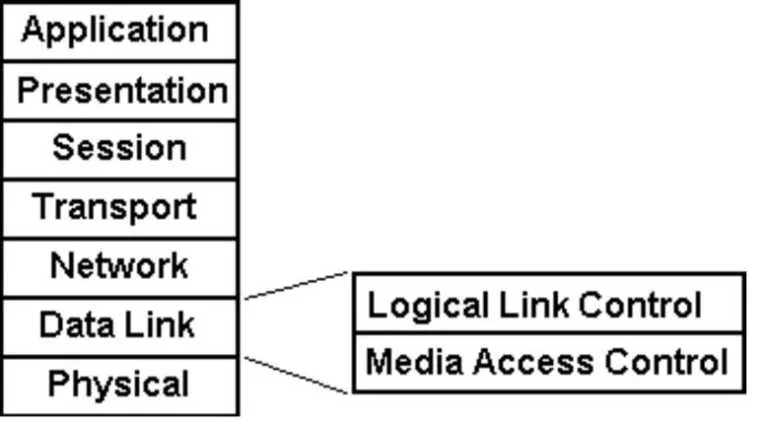
A browser which is a user agent works on layer 7 i.e. application layer adds a header to the data and forwards it to the transport layer. The transport layer adds another header to the packet which is called segment on the transport layer.
Then the data passes down to the network layer, which adds another header on top of what it received from the transport layer and forwards the packet to the data link layer. The network layer also adds the source IP address and the destination IP address in the packet.
Data link layer adds another header on top of it and forwards that to the physical layer. The packet at the data link layer is called frame.
And now the game begins –
The frame from the data link layer is converted to binary data (0’s and 1’s) and sent to Switch (assuming that a switch is directly connected to the PC in this case) using a physical cable (from the physical layer) in where the destination MAC address is of the Switch. Here, it is assumed that you already know about the Switching, and henceforth on, the underlying switching concept won’t be discussed.
The frame is received by the Switch. The Switch forwards the frame to the default gateway, which, in the most of the cases, would be your router.
The router receives the packet and removes the network layer header. After removing the header, it looks at the destination IP address in the packet.
As discussed at the beginning of this article, each interface of the router connects to an IP network, the router looks the best match for the destination IP address in its routing table. After finding out the best match, it forwards the packet through that interface to that network. The same procedure is repeated until the packet reaches its destination.
Routing Table
For the Routing purpose, each router maintains a database table called the routing table. Each routing table will usually have the IP address of the network of the forwarding link. With the advancement in the routing algorithms, Routing tables also known as the Routing Information Base (RIB) started to have some metrics associated with those routes.
Just for the understanding purpose, a metric associated with the routes could be the distance (hops) to another node, link speed of the associated links or ISP rules, etc.
Routing Table is usually stored in the RAM of the router. It does not only have the information about the directly connected networks (via interfaces), but also, it has information about the remote networks.
Longest Prefix Matching (LPM)
Longest prefix matching is the backbone algorithm in finding the next hop for a packet moving towards its destination. When a router sees the destination IP address, it might happen that in the CIDR notation, there are more than one networks where the packet can be forwarded to. So to avoid the tie, LPM is used.
Since some of the busiest routers receive very heavy traffic per second, a normal search algorithm implemented at the router might not work properly. To accelerate the prefix matching, routers use assistive hardware which works as an accelerator in doing LPM.
There are two such famous hardware accelerators which are used in the LPM.
- CAM (Content Addressable Memory)
- Trie (A data structured tree)
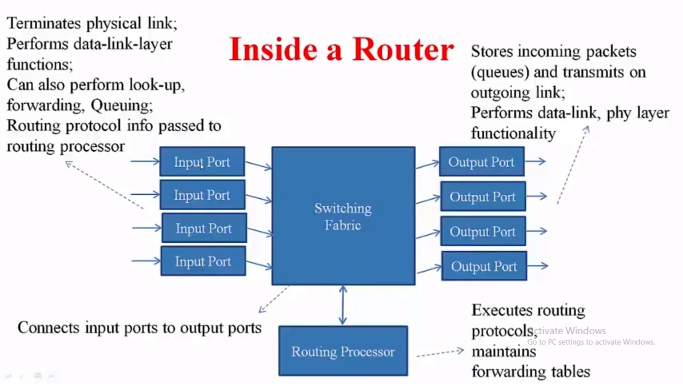
Inside a Router
A router has four building blocks.
- Input port
- Switching fabric
- Routing Processor and,
- Output Ports
Input Ports
At the input ports, the physical link terminates. If you realize here, the data is coming from the Switch (as per the scenario discussed above). So, in this case, the router should be able to read the data link layer headers as well as the network layer headers. Besides, the router also maintains a copy of the forwarding table at the incoming ports. We will discuss that later in this article under Router Performance.
Here is a question for you:
Can packets get queued at only one input port while not on others? If so, then under what conditions? Leave your answers in the comment at the end of the article.
Switching Fabric
Let us understand the switching fabric with an example. Let us say the router receives a packet on the first input port. However, when the packet was read by the router, and after performing LPM, it was found that the packet should be forwarded to the next network through the third output port. That’s where the switching fabric comes into the play.
Switching fabric can be said as one kind of integrated circuits which helps the router in making a decision on forwarding a packet to the particular output port.
Routing Processor
Routing processor maintains the routing table. When a network administrator implements a routing algorithm, it is the routing processor which helps the network admin to achieve the desired routing protocol’s correct implementations.
Output Port
If the input port reads the data link & network headers then the output port puts them back on the place. It also performs the physical layer functionalities by sending the data out of the router in bits.
Router Functions
A router performs a lot of functions such as IP lookup, packet forwarding, maintaining the routing table, etc. These functions can be broadly divided into two functions
- Data path functions and,
- Control functions
Data Path functions
Data path functions are mostly related to the functions that are performed on the datagrams. Some examples of these functions are
- Forwarding a datagram
- checksum calculation on the packet to find out if the received packet is erroneous or not
- Scheduling the packet on the outports before forwarding them. The scheduling can be done as per the QoS (Quality of Service) and can include FIFO, FCFS, etc.
- The special hardware accelerator that we discussed in the paragraphs above helps the router in the data path functions.
Control functions
Besides packet forwarding, a router must also perform the other functions infrequently and on-demand. Unlike datapath functions, these functions are implemented in the software.
- For example, when we login to the router and perform some router settings, that’s a part of the router control functions.
With so many functionalities in place, it is also necessary to understand the limitations that might curb a router’s performance.
Router Performance Limitations
Lookup speed > line speed
It is evident. If the lookup speed of the router (the speed at which the router looks up the forwarding/ routing table and forwards a packet to the outgoing port) is lesser than the line speed (the speed at which the router receives a packet). Then, there we will be a long queue of the packets at the input port which will eventually result in dropping off the packets from the input ports itself.
To minimize the delay and losses, a copy of the forwarding table is also maintained at the input ports of the router.
Scenario
Let’s say the line speed of an input port is 1GBps. So, the input port can receive up to 1,07,37,41,824 Bytes of data per second.
Let us say, one packet is of 32 Bytes. Then the router is receiving around 33,554,432 (1,073,741,824/32) packets per second.
If the lookup speed is not more than the number of packets mentioned above then just imagine how many packets will be dropped per second. In this case, the router should be able to lookup around 33 million packets per second.
Switching Speed > N x Line speed
Here, the switching speed is the speed with which switching fabric forwards an incoming packet to the outgoing port. Let’s say, there are N output ports. Then, the Switching speed has to be faster than the N times line speed of the outgoing ports. Otherwise, there will be a long queue of the packets, and eventually, the packets will get dropped.
Other Notes
- Most routers store the OS in ROM.
- RAM represents the volatile working area of the router in where routing table, ARP table, running configurations are stored.
- RAM can also be used as the buffer location if the packets are queuing up
If you are more interested in the similar topics, here is our coverage on computer networks.